


Test Bodies and Reference Blocks for PT
Test Bodies and Reference Blocks for Penetrant Testing
Sensitivity of inspection media, quality of intermediate cleaning and control of the entire penetrant process are determined by
test bodies which are metal panels with defined roughness, provided with standardised artificial cracks (defects).
|
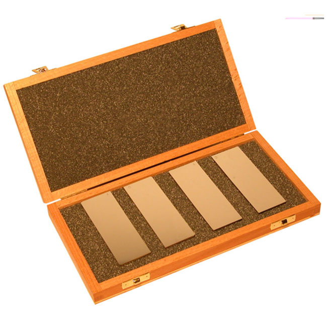
Test body JIS Z 2343 |
|
 |
The test body is used to determine the sensitivity of penetrant systems and for comparing two penetrants, one of which can be taken for standard. It consists of two test panels which are bronze planes 100 х 35 х 2 mm, plated with a NiCrlayer. Several crosscut cracks are made in the nickel-chromium plating, the depth of cracks equals the thickness of the NiCr-plating. The bodies are designed in 4 types – with plating thicknesses of 10, 20, 30 and 50 μm. The ratio of crack widths to their depth equals 1:20. Each test panel is delivered with a certificate according to EN 10204, type 3.1 B, which certifies its conformity to EN ISO 3452-3. The test panels with crack depths of 10, 20 and 30 μm are used for testing of the sensitivity of fluorescent penetrant systems. The sensitivity of contrast penetrant systems is determined by panels with crack depths of 30 and 50 μm. |
|
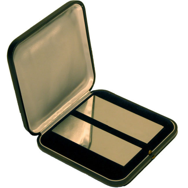
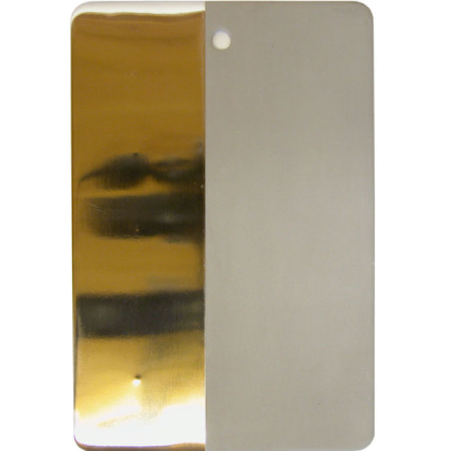
Reference Block No.1 (EN ISO 3452-3) |
|
 |
Art.No. 127.400.001 – to be delivered with a certificate The Type 1 Reference Block for testing the sensitivities of fluorescent and visible penetrant systems consists of 4 nickel-chromium plated panels with 10, 20, 30 and 50 μm thickness of plating respectively. The panels with crack depths of 10, 20 and 30 μm are used for determination of the sensitivity of fluorescent penetrant systems. The sensitivity of visible (contrast) penetrant systems is determined using the 30 and 50 μm plated panels. The Type 1 panels are rectangular in shape with typical dimensions of 100 x 35 x 2 mm. Transverse cracks are made in each panel by stretching the panels in longitudinal direction. The width to depth ratio of each crack should be approximately 1:20. A declaration stating compliance with EN ISO 3452-3 and in line with EN 10204, Type 3.1 B shall accompany each test block. |
|
Reference Test Panel No.2 (EN ISO 3452-3) |
|
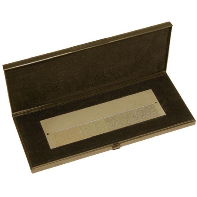 |
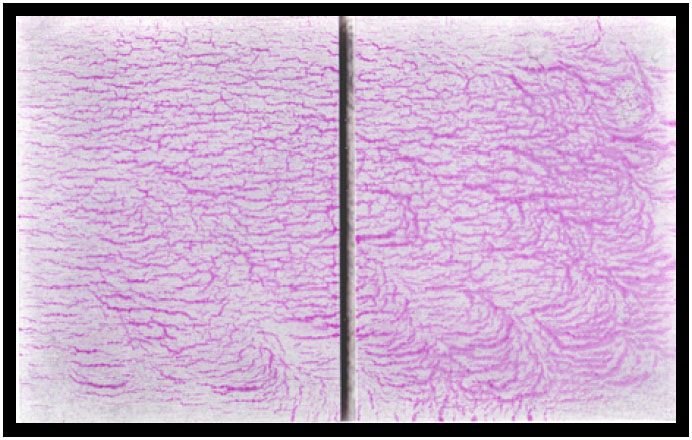
The Reference Test Panel No. 2 is an austenitic plate which is chromium-plated and provided with four fields (25 x 35 mm) of different surface roughnesses (Ra = 2.5 μm, Ra = 5 μm, Ra = 10 μm and Ra = 15 μm) on the one half and 5 star-shaped crack patterns of different sizes on the other half. The roughened fields are used for control of the intermediate washing-off. The star-shaped cracks in the chromium plating are generated by ball stamping from the rear side. The indication on the reference test panel gives no suggestion of the indication on the part under test. |
|
Test Panel ASME V |
|
 |
The ASME V panel is used for testing of the penetrants indication sensitivity. Due to the division of the test panel into two parts it is possible to compare two different penetrants.
The test panel is an aluminum block of 80 х 50 х 10 mm divided by a notch (50 х 2 х 1.5 mm) into two parts. Because of a special thermal treatment the panel surface crack pattern is produced, which is different on the front and rear side of the test panel. |
|
Test Panels WTP-1 and WTP-2 |
|
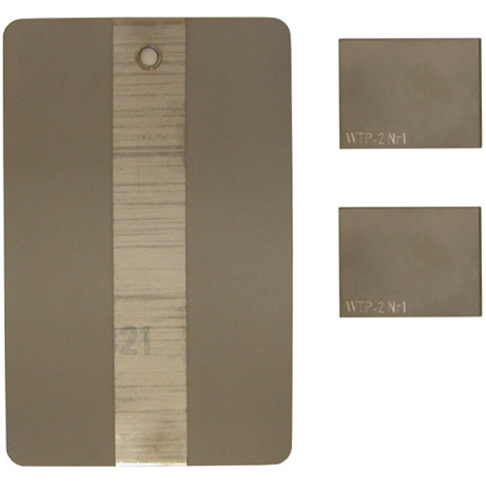 |
The test panels are designed to evaluate the removability of fluorescent penetrants according to the requirements of AMS 2644C. WTP-1 is a stainless steel 4×6 inches panel with two parallel “medium rough” strips, each 6 × 1.5 inches, separated by a smooth 1 inch strip. WTP-2 is a set of two equal 1.5 x 2 inches panels produced from a single sheet and is also used for assessment of fluorescent penetrants removability. |
|
PSM-5 Test Panel |
|
 |
The PSM-5 control block is used to test the manual or automatic (semi-automatic) penetration process, in accordance with Pratt & Whitney Aircraft TAM 1460 40. PSM-5 is a rectangular panel made of stainless steel, with dimensions of 10 x 15 cm and a thickness of 2.3 mm. The chrome-plated left band contains 5 star-shaped cracks that are arranged according to their size. The pattern of cracks differs from one panel to the other. The right half is sand-blasted and is used to assess the degree of penetration removal. The panel should not be used to compare different penetrating liquid systems. |


